Conducting shell
Modular shell structure, which is composed of one primary shell and one correction shell, is applied to KTX, as shown in figure 4. In order to guarantee a high plasma quality, a primary passive copper shell with a thickness of 1.5mm (20ms penetration time) will be attached tightly to, but insulated from the vacuum vessel to stabilize fast-growing MHD modes, especially in the current ramp-up phase. The primary shell consists of four pieces as shown in figure 4(b). The whole vacuum vessel is coated by a thin ceramic layer for insulation purpose, then the four copper pieces are attached closely to the vessel. The distance between the primary shell and outer surface of the vessel is 5mm, which allows enough space to accommodate magnetic field sensors while still maintains a small proximity. On the outboard side, the up and down pieces are connected and short circuited by bolted copper plates, while on the inboard side the up and down pieces are not connected to serve as a horizontal gap, which ensure the feasibility of possible PPCD research in the future. Two vertical gaps are also reserved in the primary shell, corresponding to the gaps in the vacuum vessel at the same toroidal locations. This primary shell structure provides the basic plasma equilibrium together with EQ coils during the current ramp phase. The small proximity of the primary shell also provide some benefits to stabilize the fast ideal MHD instability.
The discontinuity resulted from the vertical and toroidal gaps will produce large error field. The radial magnetic fields are generated near those gaps by the eddy currents, which will deform the shape of equilibrium surface and cause disruption and mode locking if their amplitudes are large enough. To compensate these error fields, the correction shell structure is applied.
Two semi-circular copper sheets insulated from other copper sheets, are used to cover the horizontal gap on the inboard side as the purple part shown in figure 4(c). Another four copper components (extended 30o in toroidal direction and insulated from the else) are placed closely to the two vertical gaps, shown as the blue parts in figure 4(c).
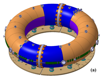
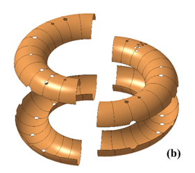
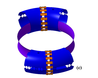
Figure4 (a) The final assembly of the whole conducting shell. (b) The four pieces of the primary shell. (c) The correction shell structure.
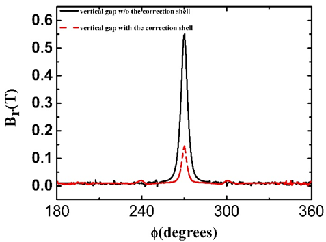
The two neighbor parts besides one vertical gap are short circuited. The simulation result of the advantage of this correction shell is illustrated in in figure 5. The two lines show the radial field distribution from 180o to 360o at the edge of plasma, while the position of one vertical gap is at 270o. One can see that radial magnetic field is greatly reduced by around 70% with the correction shell. To further reduce the error field near the vertical gap, 24 small saddle coils will be installed over each vertical gaps to control the radial magnetic field in real time.
 联系电话:
联系电话: 联系邮箱:
联系邮箱: 联系地址:
联系地址: