Ohmic field coils and
equilibrium field
The poloidal field coils are designed with the capability of 1MA plasma discharge, and the design of poloidal field power supply is applied to 0.5MA plasma discharge. The KTX polodial field coils are divided into two groups. The first group (26 OH coils in red shown in figure 6) consists of OH field coils, which provides the most of the flux swing. The other group (12 EQ coils in blue shown in figure 6) consists of EQ coils which mainly controls plasma position and minimizes the mismatch of the poloidal magnetic fields inside and outside of the vacuum vessel shell to reduce the eddy current, which is responsible for error field near the vertical gaps of the vessel.
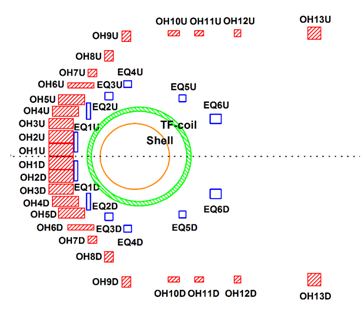
Figure 2: Vertical cross section of KTX magnetic field coils
Ohmic field coils
The design objectives of the KTX OH system are (1) to have the potential to provide 5WB poloidal filed flux swing; (2) to keep the coil-to-ground voltage and maximum terminal voltage as low as possible; (3) to minimize vacuum stray field generated by OH coils in the plasma area to less than 20Gauss; (4) to allow the OH coils and EQ coils to share the same main power supply during the current ramp-up phase and to provide additional currents to individual EQ coils during the plateau of the plasma current with additional power supplies as needed. Decoupling between those two groups of coils is also required; (5) to satisfy the requirement of double-C structure by allocating enough space between the coils and vacuum vessel; and (6) to allow accessibility of diagnostic tools and support structures by optimizing the placement of the poloidal coils.
There are 26 OH coils (228 turns in total) distributed with an up-and-down symmetry. To induce 250V toroidal loop voltage required for reliable breakdown of the gas and to ramp up plasma current within 10ms, the total power supply voltage is approximately 50kV. Therefore, the coils and the power supplies are divided into three groups to reduce the voltages on each capacitor bank and between terminals. The distribution of the OH coils is show in figure 1. The coils OH1 to OH7 mainly provide the flux swing needed, while the coils OH8 to OH13 are mainly used to minimize the stray field in the plasma area. No OH coils are placed outboard the vacuum vessel to allow the double-C structure. The design of the OH coils has been optimized, by adjusting the position of the coils and the number of turns in each coil. We can see that a low vacuum field (< 20Gauss) is achieved in the plasma area in figure 1 with the maximum OH coil current 52kA per turn for a 5WB poloidal field flux swing.
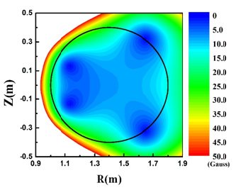
Figure 2: Stray field generated by current of OH coils. The black circle indicates the cross section of the vacuum vessel
KTX equilibrium field system
The design of the KTX equilibrium field system accommodates the following requirements: (1) to provide proper vertical magnetic field for plasma equilibrium; (2) to effectively decouple the EQ field coils from the OH coils so that the current through each EQ coil can be controlled independently; (3) to minimize the mismatch of the poloidal magnetic fields inside and outside of the vacuum vessel shell, so as to reduce the error field at vertical gaps; (4) to satisfy the space requirement for double-C structure; (5) to satisfy the accessibility for diagnostic tools and the support structure; and (6) to reduce the demand on the power supplies for EQ coils;
As shown in figure 1, the 12 EQ coils (marked blue) are distributed with up and down symmetry. The vertical magnetic field required is about 0.17T to balance the radially outward force on the plasma with a plasma current of 1MA. The induced current on the vacuum chamber has been minimized to almost zero during the design for a smoothing flux boundary along the surface of conducting shell.
To realize the double-C structure, some of EQ coils have to be placed radially outward rather than close to the plasma boundary. As seen in figure 6, the EQ coils is relatively far from the boundary of the vacuum vessel and the conducting shell, the vertical distance between the EQ6U and EQ6D coils is around 0.8m and the closest distance between the two outside coils (EQ6U or EQ6D) to the TF coils is 0.3m.
 联系电话:
联系电话: 联系邮箱:
联系邮箱: 联系地址:
联系地址: