The ripple depends also on the radial and poloidal locations. Figure 1 shows the maximum ripple as functions of the radial positions at several selected poloidal positions. It can be seen that the ripple decreases sharply from the plasma boundary to the plasma center. The maximum ripple in the plasma area is less than 10%. The TF coils are divided into 4 groups and arranged evenly. Each group consists of 6 coil sectors. This design allows different combinations of serial or parallel connections of the 4 groups to change the total inductance L . For experiments requiring fast-changing current in TF coils, such as PPCD and OFCD, this provides operation flexibility and reduces voltage requirement on the TF power supply.
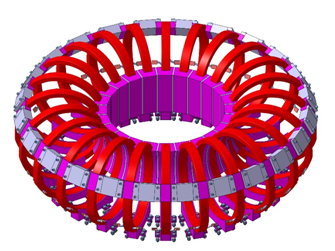
Figure 1. Three-dimensional view of the structure of TF coils of KTX. The silver blocks and the purple blocks between the red coils are used to support the coils and to counterbalance the torque due to the vertical magnetic field. It shows the toroidal field coils the support structures. The toroidal field ripple is defined as the ratio of the magnetic field componentperpendicular to the toroidal direction to the component in the toroidal direction. The maximum ripple occurs in the middle between the two TF coils.
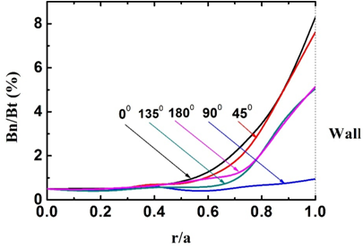
Figure 2:Toroidal magnetic field ripple profile along the radial position at different poloidal locations. The maximum ripple is at the outboard side at 00 in poloidal position, and the minimum ripple is at the up or down position of the vacuum vessel at 900 in the poloidal direction.
Toroidal field coils
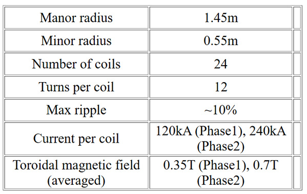
Table 2 shows the main geometrical and the electrical parameters of the TF system. Each of the 24 TF coils has 12 turns and the total number of turns is 288.
Table2. Parameter of KTX TF coils
 联系电话:
联系电话: 联系邮箱:
联系邮箱: 联系地址:
联系地址: