The OH and EQ coils are energized by the same poloidal field power supply during the plasma current ramp-up phase. The total ampere turns of the EQ coils is designed to be equal in magnitude and opposite in direction to the plasma current. Six auxiliary power supplies are used to adjust the currents through the EQ coils. To decouple the EQ coils from the OH coils, the number of turns and connection patterns among those coils has been optimized. Figure 8 shows the simplified model of poloidal field coils and the corresponding power supplies. The OH coils are divided into three branches with the same self-inductance, and all the coils are connected in series. The three branches are arranged to generate equal voltages between terminals. Because the current through the EQ coil branches is much smaller than that through the OH coil branch, the currents through the three OH coil branches are approximately equal. The EQ coils are divided into six branches, with two branches connected in parallel to one OH coil branch as shown in figure 8. In KTX, the equivalent self-inductance of the OH coil branch and the equivalent mutual inductance between the OH coil branch and each of the two parallel EQ coil branches are almost the same ( LOH = MOH_EQ ). In this case, the effect on the EQ coils from OH coils cancel with each other and the currents through the EQ coils ramps up proportionally with the plasma current as required.
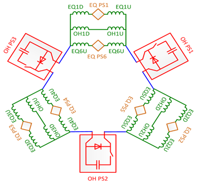
Figure 8. Poloidal field circuit diagram. The red parts indicate the OH power supply circuits, and the green parts indicate the EQ power supply circuits. The letters U and D after EQ and OH distinguish the symmetrical up and down pairs.
OH power supply
The schematic block diagram of OH power supplies is shown in figure 9. The capacitor COH1 with a maximum 50kV voltage and 2.85mF capacitance is used to ramp up plasma current quickly. COH2 with a maximum 5kV voltage and 0.1F capacitance joins the discharge when the voltage on the COH1 bank drops to the charged voltage on COH2 to maintain a flat plasma current. A crowbar is used to provide a current path when the plasma current ramp down at a later time. This power supply will be divided to 3 power supplies as shown in figure 8.
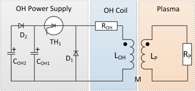
Figure 9. Conceptual design of OH power supply circuit. The plasma is simplified as a circuit with an inductor and a resistance connected in series.
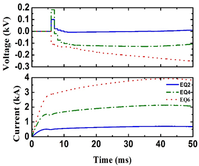
Figure 10:
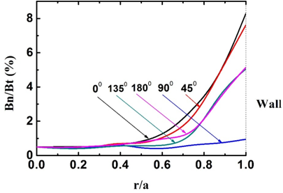
Figure 11: Toroidal magnetic field ripple profile along the radial position at different poloidal locations. The maximum ripple is at the outboard side at 00 in poloidal position, and the minimum ripple is at the up or down position of the vacuum vessel at 900 in the poloidal direction.
Equilibrium field power supply
In an ideal situation, the currents in the EQ coils should increase proportional to the OH coil current or plasma current. Once the turns and locations of EQ coils are set, the mutual inductances among them are also fixed, and the ratios between plasma current and each EQ coil remain constant in the circuit modeling when the resistances of coils and plasma are ignored. When the circuit resistances are included, additional current drive is needed for each EQ coil to achieve the desired poloidal field configuration and magnitude that match the plasma current at all times. Due to the up-down symmetry of the EQ coils, six independent EQ power supplies are planned to control the coil current during the discharge. The EQ power supplies may be controlled by 1 kHz PWM (pulse width modulation) units to facilitate feedback position control. The EQ power supplies are not activated during plasma current ramping phase, because the rapidly changing plasma current would induce a high voltage on the EQ coils. During this phase the low voltage EQ power supply is actually bypassed to allow OH power supply to drive current through the EQ coils. In a circuit simulation of PWM control, the resistances of EQ coils and plasma are included for a 0.5MA plasma current. Those EQ power supplies are turned on at 7ms when the plasma current reaches its maximum. The waveforms of voltage and current for EQ2 coil, EQ4 coil and EQ6 coil power supply are shown in figure10. The peak voltage for the EQ power supplies is less than 350V and the peak current is less than 4kA.
Toroidal field power supply system
The maximum energy stored in the capacitor bank is 0.6MJ. The reversal of the field is realized through discharging of two capacitor banks with opposite voltages. During the plasma current rump-up phase, the single turn current through the TF coils can be reversed from 10kA to -1kA within 10ms. Figure 13 shows the schematic diagram of the TF power supply for KTX.
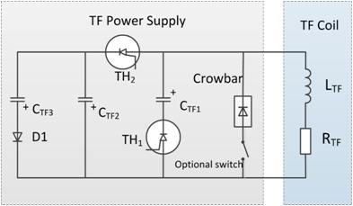
Figure 13. Schematic of the TF circuit. CTF1 is a reversible capacitor. The TH1 is switched off when TH2 is turned on for reversed toroidal field
Three capacitor banks and high voltage thyristor switches are used in this circuit. A calculated waveform of the TF circuit is shown in figure 14. This set of power supply can also be used for low q discharges in tokamak configuration, while the optional switch is turned on to connection the crowbar to the circuit.
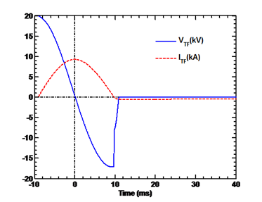
Figure 14: The time evolution of TF circuit
 联系电话:
联系电话: 联系邮箱:
联系邮箱: 联系地址:
联系地址: